

Process Hygiene · CIP Units
CIP Units: Clean-in-Place Systems for Hygienic Production
Tanks, pipelines, heat exchangers and fillers cleaned where they stand, in the same proven sequence every time, with every temperature, flow and conductivity value on record.
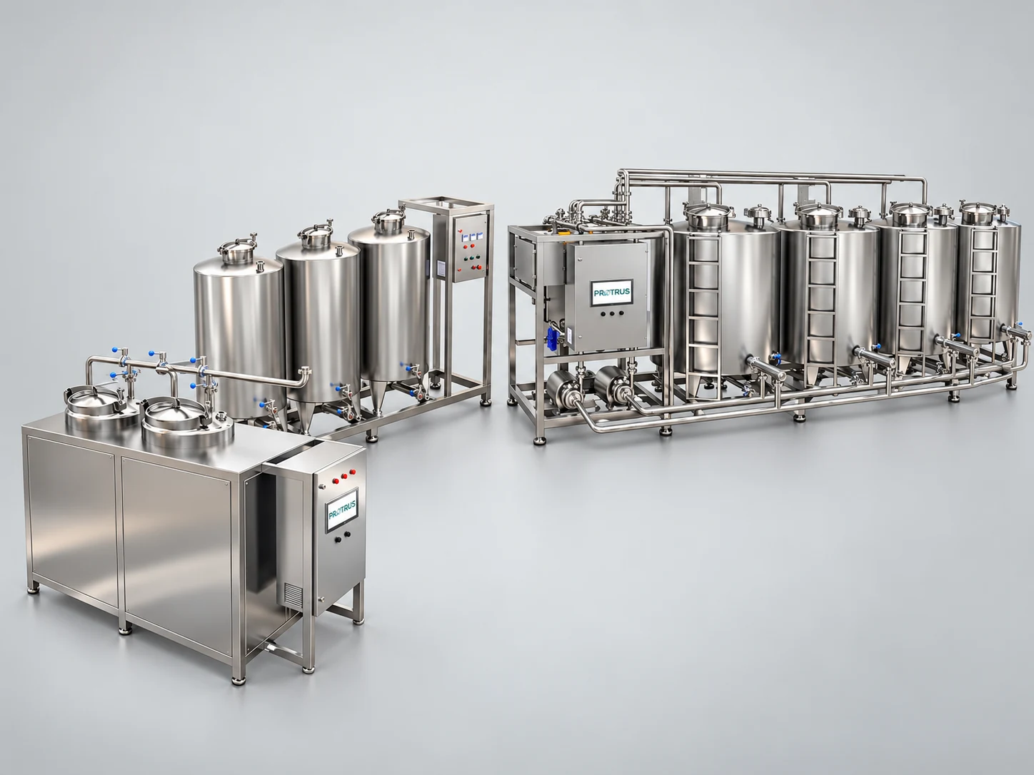
Protrus CIP units: from compact two-tank skids to four-tank CIP stations with recovery.
1.5–2.0 m/s
Minimum flow velocity in CIP pipelines
1.5–2.5 bar
Working pressure at tank spray balls
55–85 °C
Typical hot CIP temperature range
500 L – 10 m³
CIP tank sizes, mobile to central
What a CIP Unit Does
A CIP unit (clean-in-place unit) prepares, heats, pumps and recovers the cleaning solutions that clean a process plant from the inside, without opening a single clamp. It replaces manual cleaning with a closed, automated cycle of rinsing, alkaline and acid washing and sanitizing, run by recipe and confirmed by sensors.
Every food, beverage or pharmaceutical line leaves a film of fat, protein, sugar or minerals on its product-contact surfaces. If that film stays, it feeds bacteria, forms biofilm and carries taste, color or allergens into the next batch. A CIP unit removes it with four controlled forces: chemistry, temperature, flow and time.
Solutions are made up in dedicated tanks, pumped through the object at a velocity that creates turbulent flow, and routed back by conductivity so that strong chemicals return to their tanks and only clean water is reused. The result is the same cleaning result on every shift, lower water, energy and chemical use than manual cleaning, shorter downtime between batches and a cleaning record that supports HACCP, EC 853/2004, FDA 21 CFR 117 and GMP audits.
Protrus designs CIP units from a 500 L mobile skid for a single machine to central multi-tank stations that clean a whole dairy, in AISI 304/316L stainless steel, with hygienic valves, VFD-driven pumps, steam or electric heating and PLC/HMI control with full cycle records.
Jump to
Benefits of an Automated CIP Unit
Food safety.
No hidden soil or biofilm in pipes, valves and tank domes; fewer recalls and rejected batches.
Repeatable results.
The same recipe, flow and temperature on every shift, independent of the operator.
Less downtime.
Cleaning starts at the push of a button and runs while the next batch is prepared.
Lower costs.
Chemical and rinse water recovery cut water, energy, chemical and effluent costs.
Operator safety.
Closed handling of hot caustic and acid, no climbing into tanks.
Audit-ready.
Each cycle is logged with time, temperature, flow and conductivity for HACCP and GMP.
CIP Unit Configurations
From a 500 L mobile skid for a single machine to central multi-tank stations that clean a whole dairy: the configuration follows the plant, the number of circuits and how solutions are reused.
Mobile CIP unit
Tanks: 1–2 (e.g. 2 × 500 L)
Typical use
Single machines, pilot plants, sauce and caramel cookers, skids
Solution handling
Heated in tank, reused
Compact CIP skid
Tanks: 2–3 (alkali, acid, water)
Typical use
Small dairies, juice and beverage lines, one circuit at a time
Solution handling
Reuse of alkali and acid
Four-tank CIP unit with recovery
Tanks: 4 (alkali, acid, hot water, recovered water)
Typical use
Dairy, UHT and process plants with frequent CIP
Solution handling
Reuse + rinse water recovery
Multi-line central CIP station
Tanks: 4–6 + extra supply lines
Typical use
Large plants cleaning tanks and lines in parallel
Solution handling
Several circuits at once
Single-use CIP
Tanks: 1 make-up tank
Typical use
Pharma, biotech, high soil loads, allergen changeovers
Solution handling
Fresh solution each cycle
Satellite / decentral CIP
Tanks: Local tank + central chemicals
Typical use
Long distances, remote filling or reception areas
Solution handling
Short circuits, less volume
Ten steps
CIP Process: How a Clean-in-Place Cycle Works
Ten steps, each one ended by a measured value, not a stopwatch.
A CIP cycle starts before the first drop of chemical. Product left in the line is pushed out and recovered, loose soil is flushed by a pre-rinse, and only then does hot caustic remove fat and protein. An intermediate rinse keeps alkali and acid apart, the acid wash dissolves milkstone and scale, and the final rinse brings the line back to neutral.
Hot water or a disinfectant then lowers the microbial load before the plant is released. The Protrus PLC moves from step to step only when temperature, flow, return conductivity and time all meet the recipe.
A · Remove product and organic soil steps 1–5 · typical hot CIP values, final recipe set by validation
- 1Make-upWater + dosing + heatingConductivity check
- 2Product recoveryPush out with water, air or pigLess product loss
- 3Pre-rinseRecovered or fresh water3–10 min
- 4Alkaline washNaOH 0.5–2.0 %55–80 °C · 10–30 min
- 5Intermediate rinseUntil conductivity drops2–5 min
B · Remove minerals, rinse and release steps 6–10
- 6Acid washHNO₃ / H₃PO₄ 0.5–1.0 %50–70 °C · 10–20 min
- 7Final rinsePotable or RO water5–10 min · to set point
- 8SanitizationHot water or PAA80–90 °C or cold PAA
- 9VerificationATP, swab, pH, recordsBatch report
- 10Ready for productionDrained and releasedStart-up
Steps 3, 5 and 7 are switched by return conductivity, not only by time. Step 6 runs every cycle or at set intervals, depending on water hardness and mineral load.
Cold CIP (≤ 30 °C) keeps the same sequence with adapted chemistry, longer contact time and higher velocity; it suits clear juices, soft drinks and syrups.
Return routing
Strong solutionBack to its tank
Transition zoneRecovery tank or drain
Clean final rinseRecovery tank for the next pre-rinse
Temperature, Chemistry, Mechanics and Time
The four factors of Sinner’s circle work together: when one is lowered, another has to rise. Above 30 °C, each extra 10 °C makes the chemistry roughly 50 % more effective, but too much heat bakes protein onto the steel and ages gaskets.
Mechanical action comes from turbulence: pipelines need at least 1.5–2.0 m/s and a Reynolds number above 20,000, spray balls 1.5–2.5 bar. Valve clusters, tees, U-bends and dead legs are where velocity is lost first, so Protrus checks the hydraulics of the hardest circuit, not the average one.
Four factors of CIP performance
Sinner’s circle
surface
Less of one factor must be balanced by more of the others.
Temperature and return conductivity during a CIP cycle
Illustrative profile · hot CIP with acid step
Left: the four cleaning factors. Right: supply temperature and return conductivity over one hot CIP cycle; conductivity shows exactly when caustic, acid and water arrive back at the unit.
Choosing the Cleaning Chemistry
| Soil | Where it forms | Typical approach | How it works |
|---|---|---|---|
| Fat, oil, cream film | Milk, cream, sauces, cosmetic emulsions | Hot alkali + surfactant | Saponifies and emulsifies fat |
| Protein, burnt-on layer | Pasteurizers, UHT, evaporators, yogurt | NaOH 1–2 %, enzyme or oxidizer if needed | Swells and dissolves protein |
| Sugar, starch, caramel | Syrups, juice, confectionery, sauces | Hot pre-rinse, then mild alkali or amylase | Dissolves and hydrolyzes |
| Pectin, pulp, colloids | Pulpy juice, tomato, fruit preparations | Alkali + pectinase, periodic acid | Breaks gel structures |
| Milkstone, scale, minerals | Heated dairy surfaces, hard water | HNO₃ or H₃PO₄ 0.5–1.0 % | Dissolves Ca and Mg salts |
| Biofilm, microbes | Fermenters, fillers, cold lines | PAA, peroxide or hot water 80–90 °C | Oxidizes and inactivates |
Hot, Cold and Hybrid CIP
The temperature strategy follows the soil: heated, high-protein and high-fat products need hot CIP, clear low-soil lines can save heating energy with cold CIP.
Hot CIP
Alkali 55–80 °C · acid 50–70 °C · 60–90 min
The safe choice for milk, cream, UHT/ESL, high-protein, high-fat and starchy products and any heated surface.
Cold CIP
≤ 30 °C · 1.8–2.0 m/s or more
Adapted chemistry and longer contact time. It cuts heating energy for clear juices, soft drinks, syrups and other low-soil lines.
Hybrid CIP
Cold routine · hot at intervals
Cold CIP for routine cycles, hot CIP at defined intervals or when ATP, swab or heat transfer data ask for it.
Recovery
Caustic, acid and rinse water
Caustic and acid return to their tanks while concentration is right; the clean end of the final rinse becomes the next pre-rinse, saving water and effluent load.
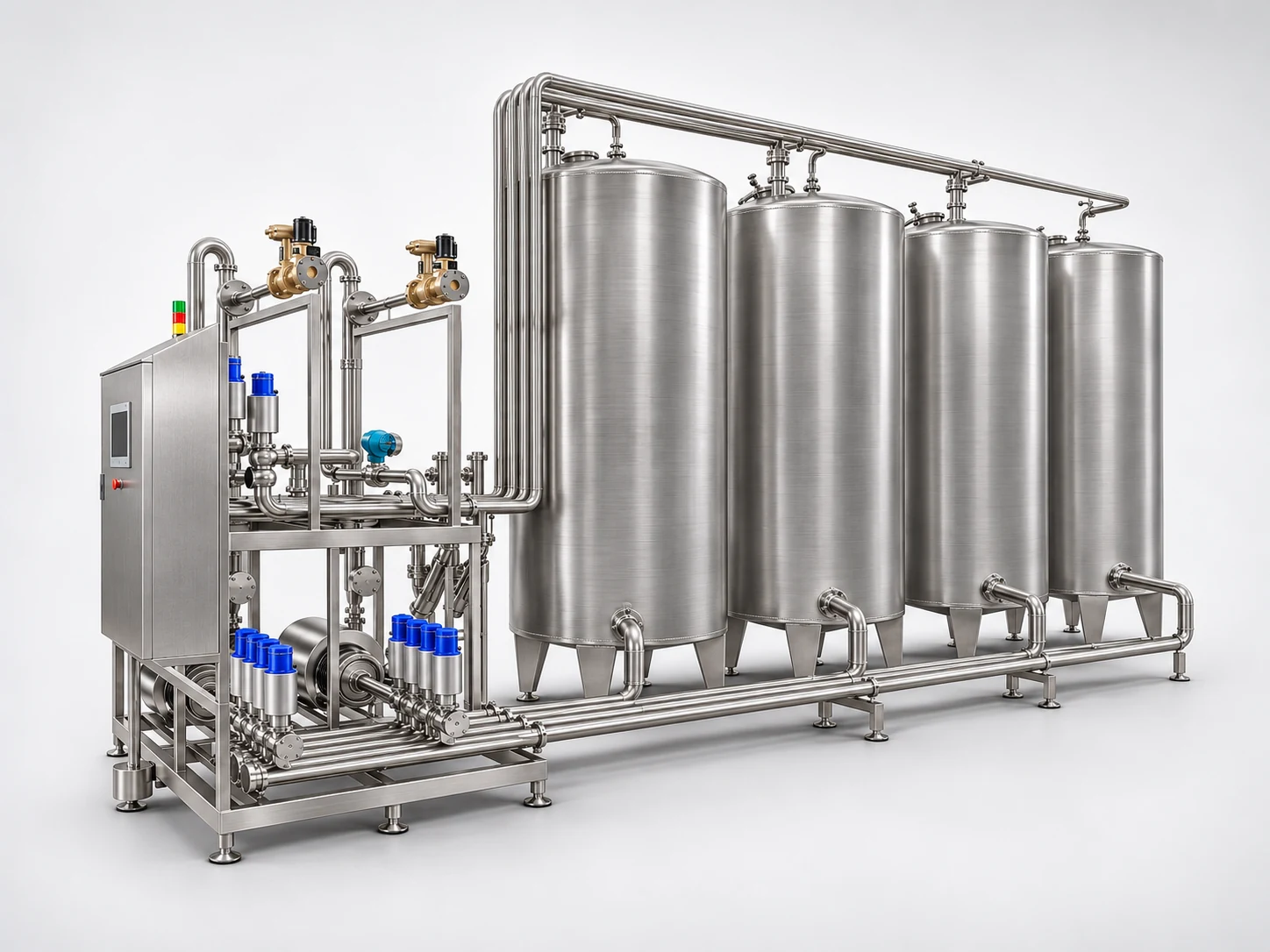
Four-tank CIP unit with valve station: alkali, acid, hot water and recovered water tanks.
CIP Unit Design: Tanks, Pumps, Heating and Automation
A CIP unit is sized for the hardest circuit in the plant, not for the biggest tank.
Before any tank is drawn, Protrus engineers list every object to be cleaned: tanks and their spray devices, pipelines with their length and diameter, heat exchangers, fillers and membranes.
From that list come the number of circuits that must run at the same time, the flow and pressure of the most demanding route, the solution volume that route needs and the heating duty. Tank count, tank volume, pump, heat exchanger and automation level follow from these numbers.
Four-tank CIP unit with recovery · basic layout one supply line · one return line · PLC recipe control
Basic layout of a four-tank CIP unit with recovery: one supply line, one return line, divert valves switched by return conductivity.
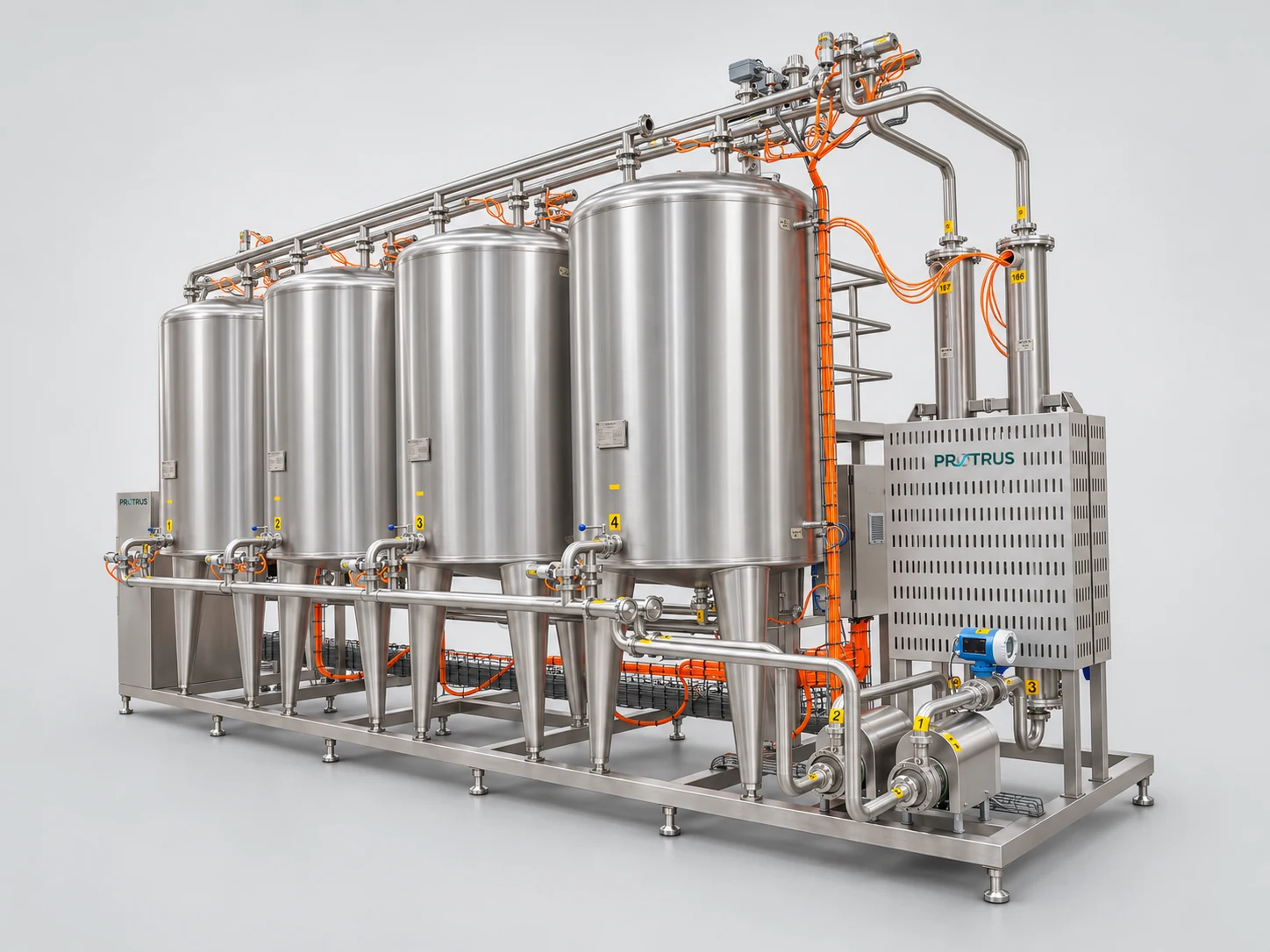
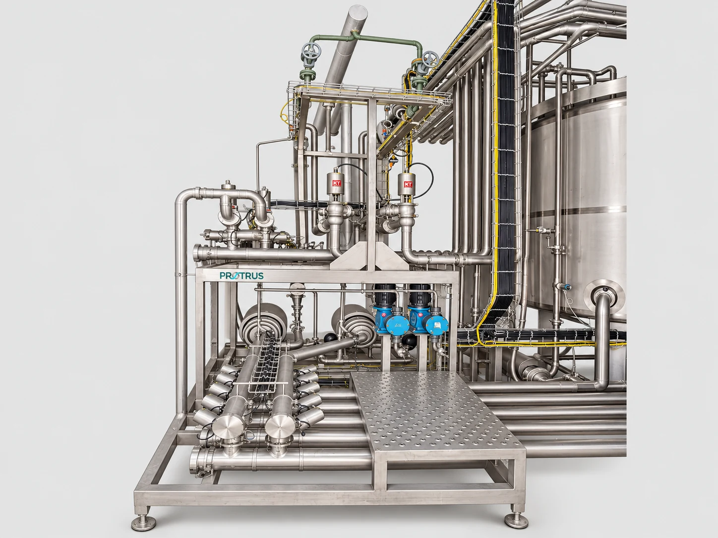
Four-tank CIP skid with tubular heat exchanger, flowmeter and CIP pumps; inset: valve manifold with supply pumps.
Main Components of a Protrus CIP Unit
Tanks. Insulated 316L tanks for alkali and acid, 304 or 316L tanks for water and recovered water; cone bottom, 360° spray ball, hygienic vent with overflow pan, Ø500 mm manhole.
Level control. High and low level switches plus a level transmitter; the low-level switch protects the pump from dry running.
Pumps. Centrifugal CIP supply pump with VFD and electromagnetic flowmeter; self-priming or centrifugal return pump.
Heating. Tubular or plate heat exchanger with steam or hot water (or electric heating on mobile units), 65–85 °C control.
Sensors. Inductive conductivity, temperature and pressure transmitters on supply and return.
Valves and automation. Hygienic mix-proof and butterfly valves, automatic chemical dosing, PLC with HMI, remote access and cycle logging.
Sizing the CIP Pump and Tanks
Flow is set by velocity in the pipe or by the spray device, whichever needs more; head adds up the losses on the way.
| Pipe | Flow at 1.5 m/s | Loss |
|---|---|---|
| DN25 (1″) | 2.9 m³/h | 0.010 bar/m |
| DN32 (1¼”) | 4.4 m³/h | 0.008 bar/m |
| DN40 (1½”) | 6.2 m³/h | 0.007 bar/m |
| DN50 (2″) | 10.6 m³/h | 0.005 bar/m |
| DN65 (2½”) | 18.5 m³/h | 0.004 bar/m |
| DN80 (3″) | 27.9 m³/h | 0.003 bar/m |
| DN100 (4″) | 42.5 m³/h | 0.002 bar/m |
Practical CIP flow per pipe size at 1.5 m/s and approximate pressure loss.
Pump flow. The larger of the pipeline need (velocity) and the spray device need sets the flow.
Pump head. Spray device pressure plus line losses in supply and return, with fittings.
Tank volume. Twice the volume of the longest line, plus a 1.5 mm film on the cleaned surfaces, plus 60 seconds of pump flow for the return delay, times a safety factor of 1.3–1.5.
Circuits. One supply pump cleans one object at a time. Parallel cleaning needs its own supply line and pump for each circuit, never an uncontrolled split of one flow.
Worked example
Flow
10.6 m³/h
A 10 m³ tank whose spray ball needs 10 m³/h at 2.0 bar, fed by a DN50 line (10.6 m³/h at 1.5 m/s).
Head
2.6 bar
100 m of DN50 supply and return with fittings adds about 0.6 bar to the 2.0 bar at the spray ball.
Duty point
12 m³/h · 2.8 bar
With a 1.1 margin on flow and head, the CIP supply pump is selected for this point.
Built for Hygiene and Service Access
Every Protrus CIP unit is built to drain fully, to be reached safely and to keep a record of each cycle.
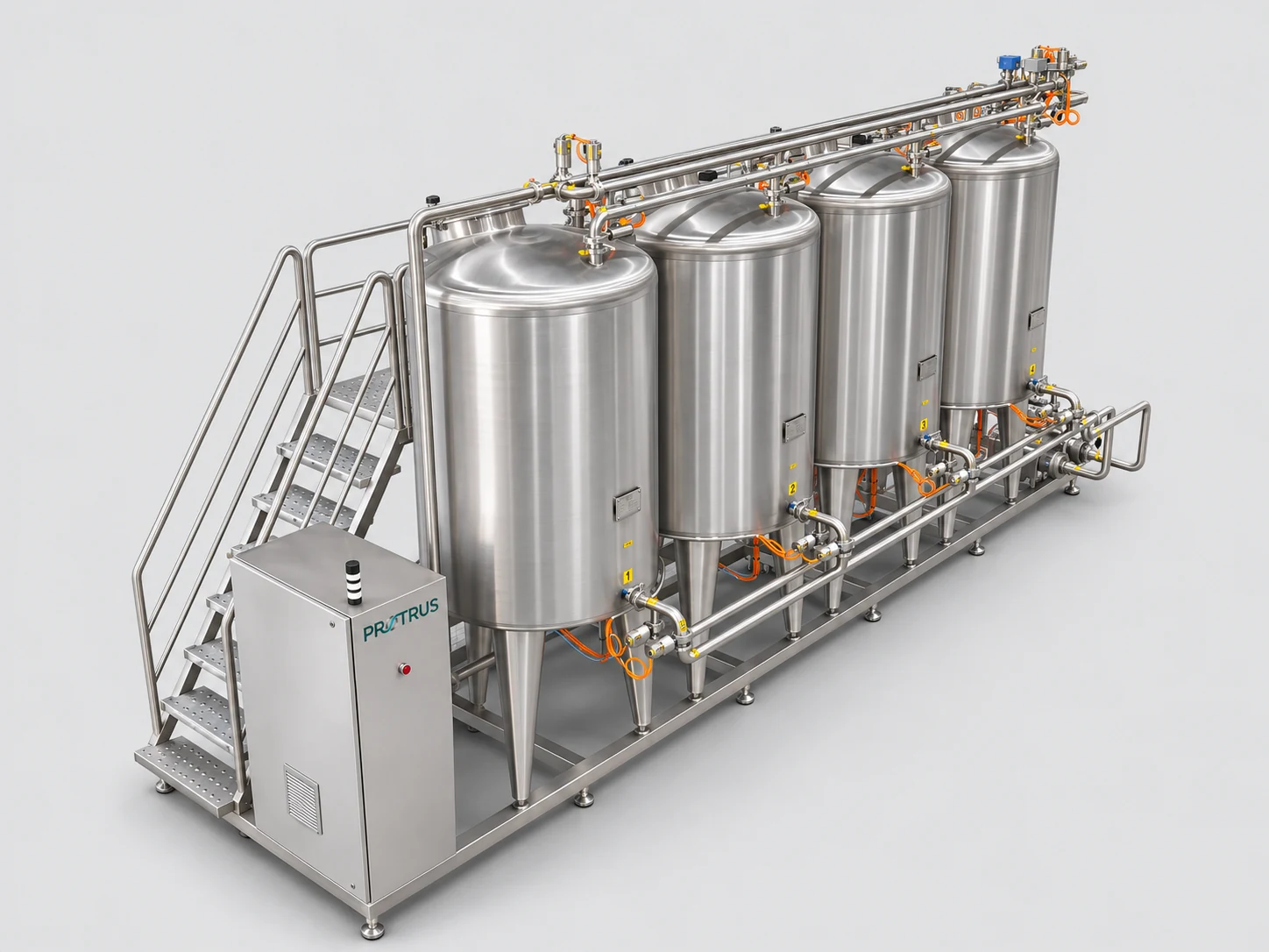
Skid with service platform and stairs
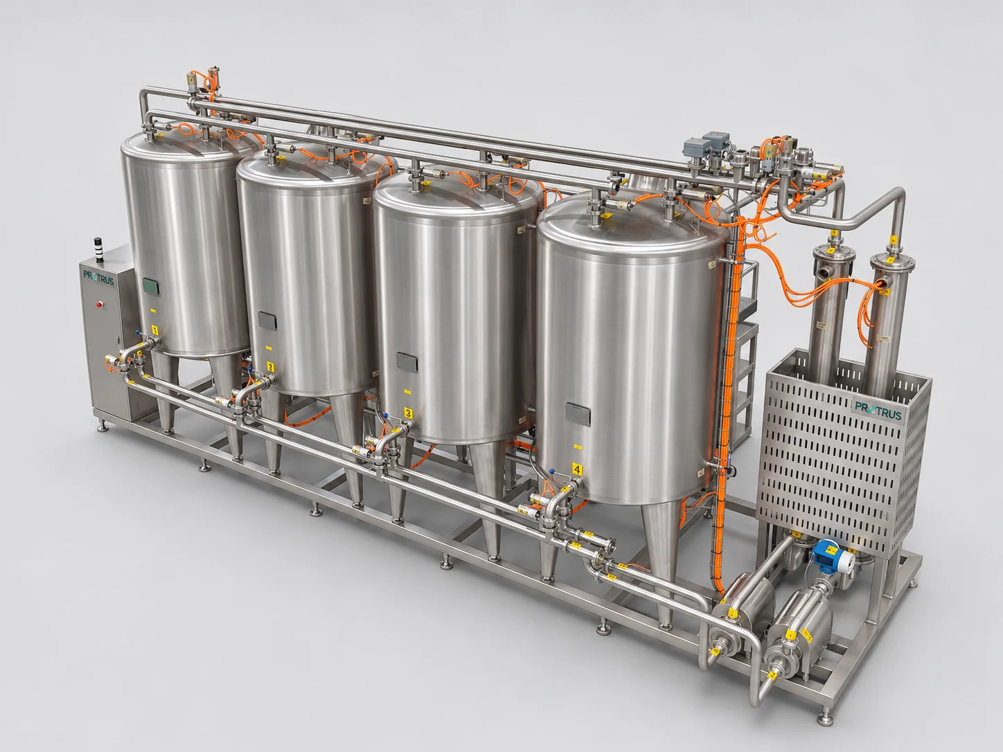
Return header with divert valves
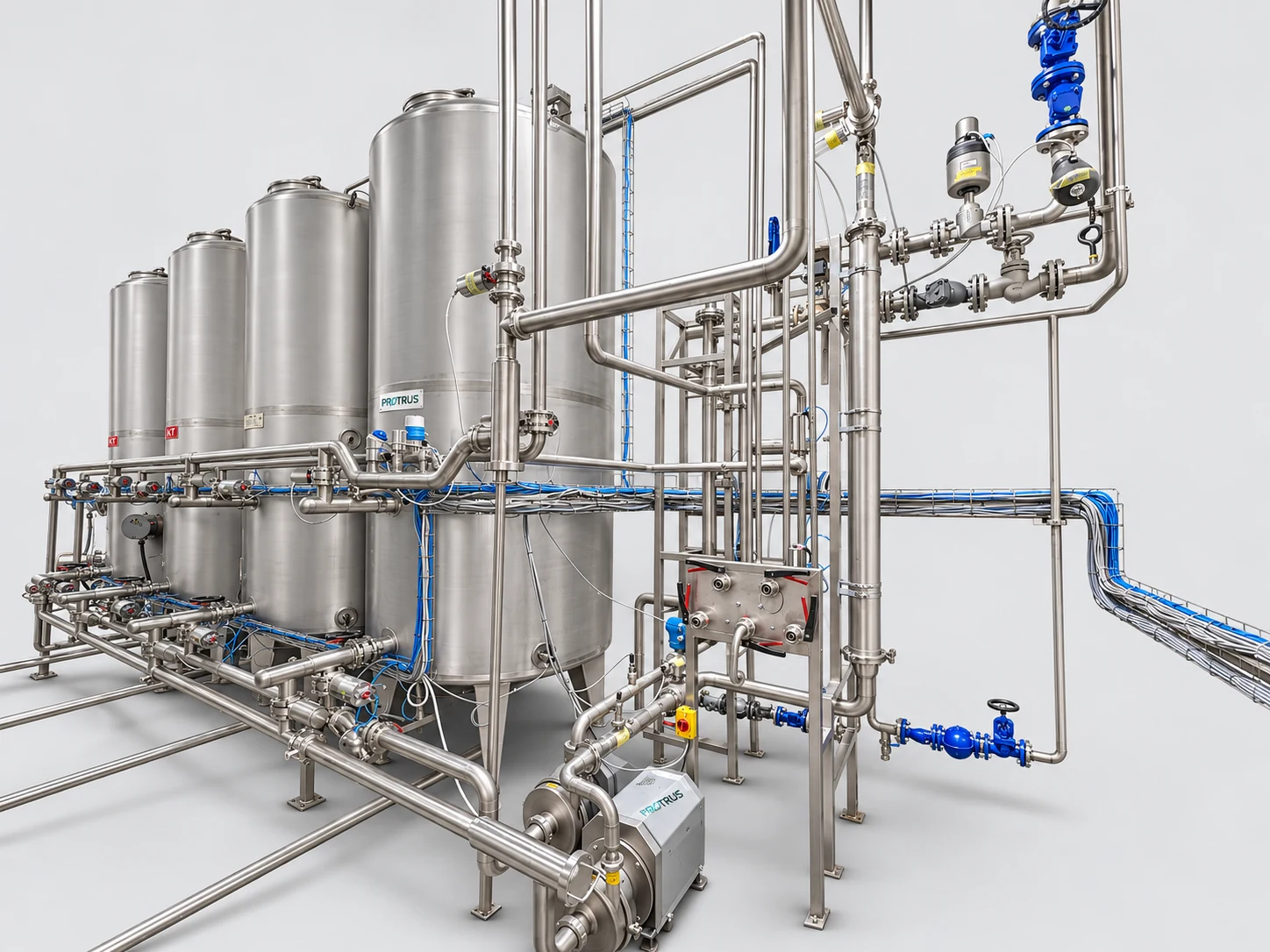
Central station with steam heating
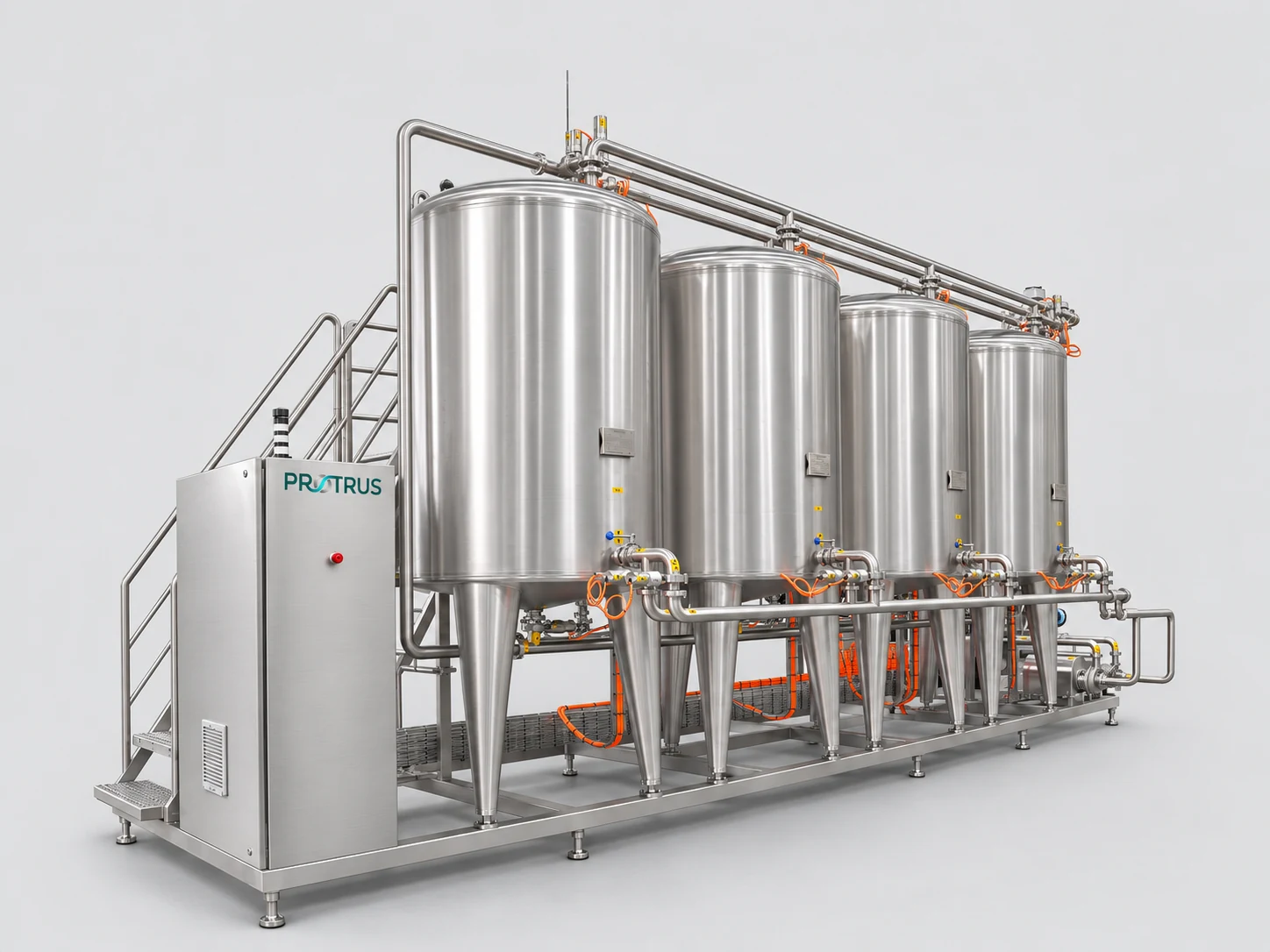
Front view: stainless control cabinet and access stairs
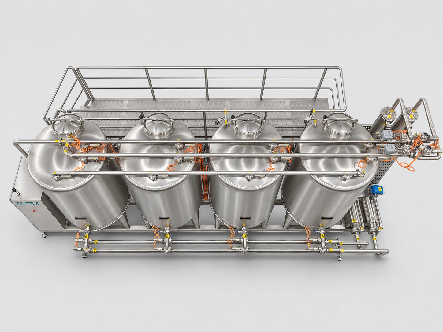
Top view: spray ball connections, pipework and guard rails
Tanks
Welded by robotic pulsed TIG to EN ISO 5817.
Pipework
EN 10357 and DIN 11851/11852, sloped for full drainage.
Utilities
For a 10 m³/h three-tank unit: steam 3 bar(g) at about 250 kg/h, RO or potable water 2 bar(g), air 6–7 bar(g).
HMI and data
Stores recipes, trends and alarms and exports every cycle to Excel or the plant MES.
CIP Applications: Dairy, Food & Beverage, Biotech, Personal Care and Pharma
The same engineering principles, tuned to the soil, the product risk and the documentation each industry needs.
Dairy and food and beverage plants are where most CIP units work, and where cleaning frequency, energy and water use matter most. Biotechnology, personal care and pharmaceutical producers add stricter demands: higher water quality, residue limits, validated recipes and traceable records.
Protrus adapts tank materials, chemistry, rinse water quality and automation to each case. For a complete dairy, see our process technology for dairy.
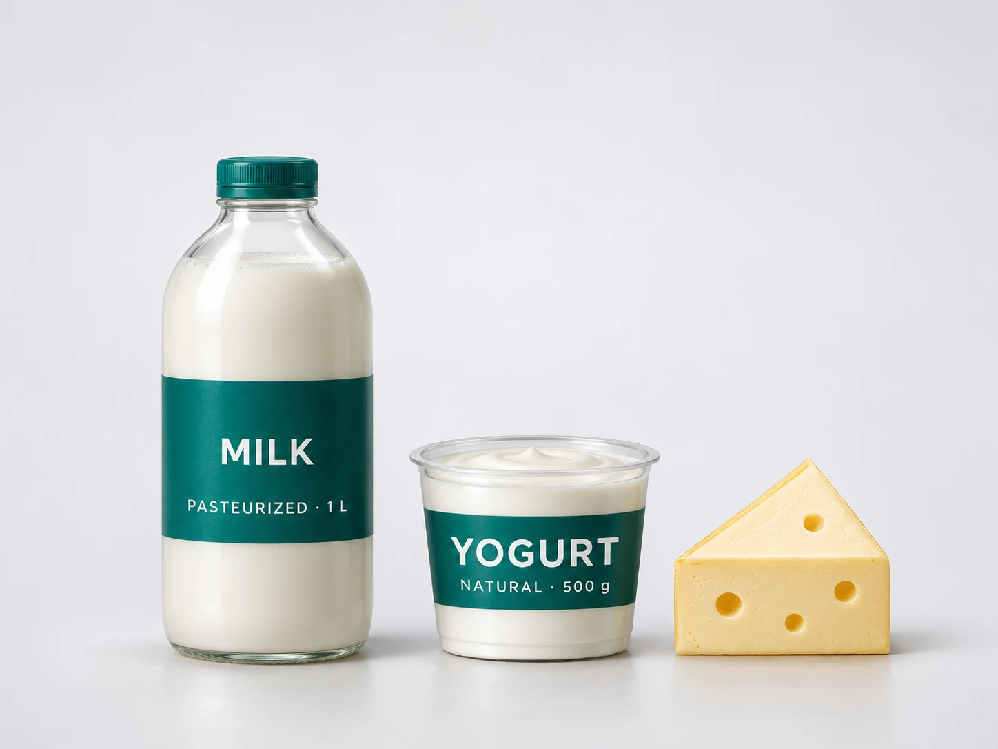
Dairy
Equipment cleaned
Milk reception, pasteurizers, UHT, separators, yogurt and cheese tanks, fillers
Main soils and risks
Protein and fat film, milkstone, spore formers
CIP focus
Hot alkali every cycle, acid daily or by run time, recovery

Beverages
Equipment cleaned
Juice and syrup lines, soft drink mixing, brewing
Main soils and risks
Sugar, pectin, pulp, flavor and color carry-over
CIP focus
Product recovery, hot pre-rinse, cold or hybrid CIP where possible
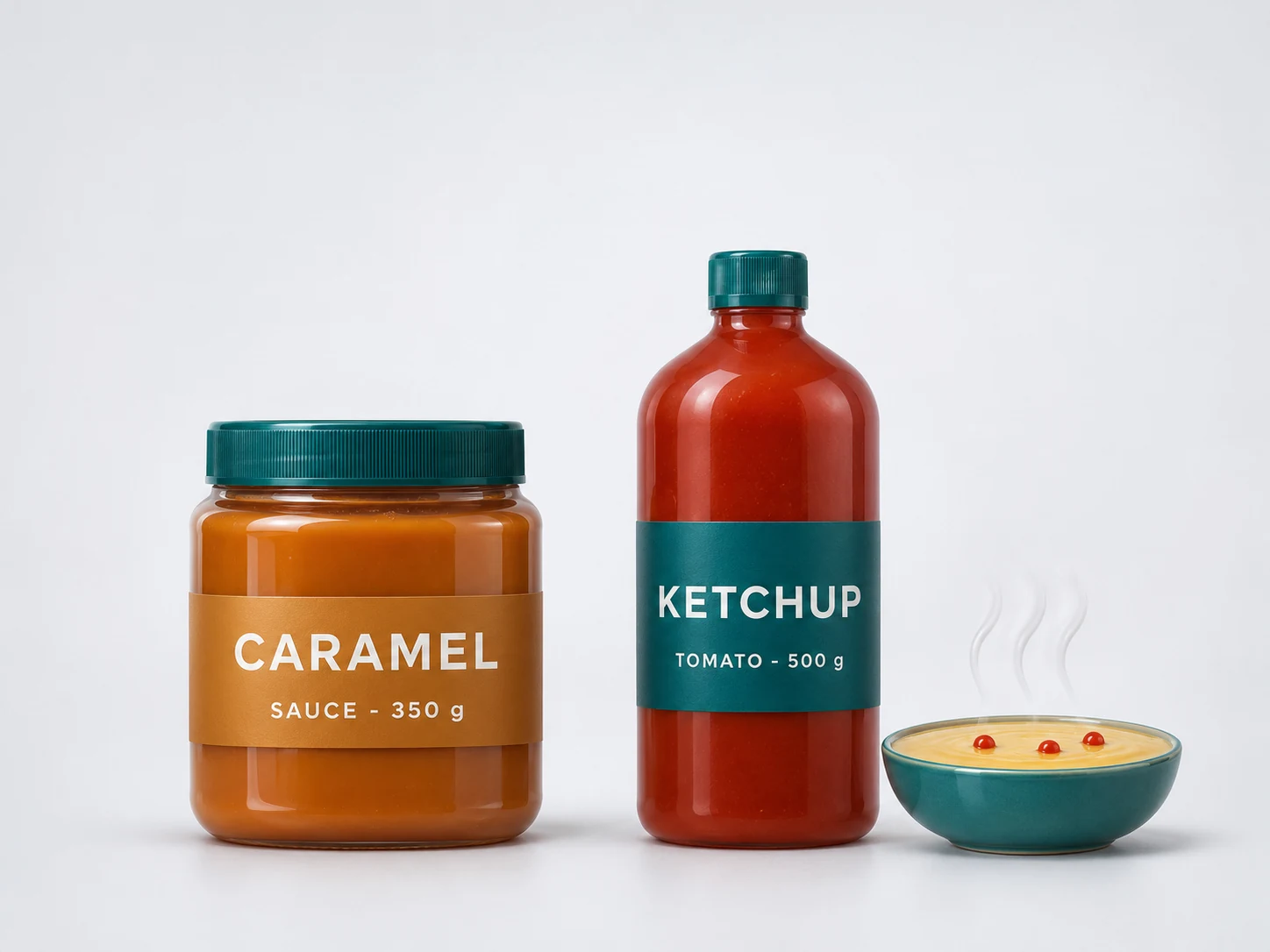
Food, sauces
Equipment cleaned
Sauces and ready meals
Main soils and risks
Sugar, pectin, pulp, flavor and color carry-over
CIP focus
Product recovery, hot pre-rinse, cold or hybrid CIP where possible
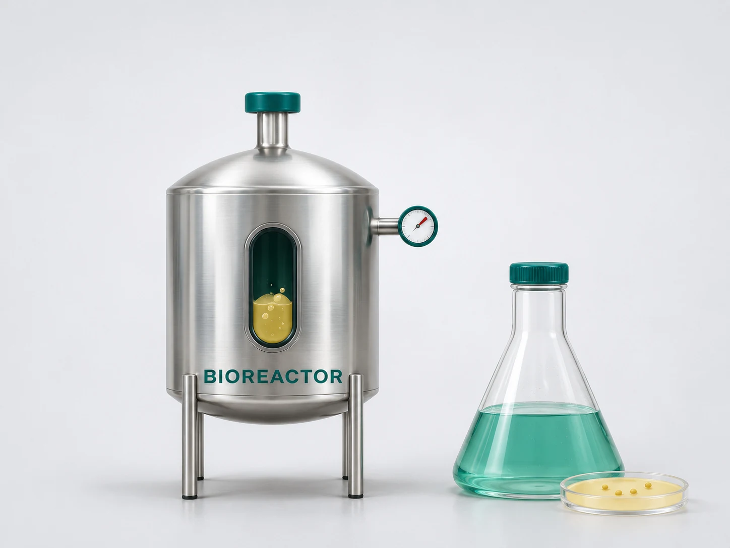
Biotechnology
Equipment cleaned
Fermenters, media and harvest tanks, centrifuges, membranes
Main soils and risks
Cells, proteins, antifoam, biofilm
CIP focus
Validated recipes, TOC and conductivity checks, CIP followed by SIP

Personal care
Equipment cleaned
Emulsion and gel mixers, storage tanks, filling machines
Main soils and risks
Oils, waxes, polymers, fragrance and color
CIP focus
Surfactant alkali, longer contact, changeover verification
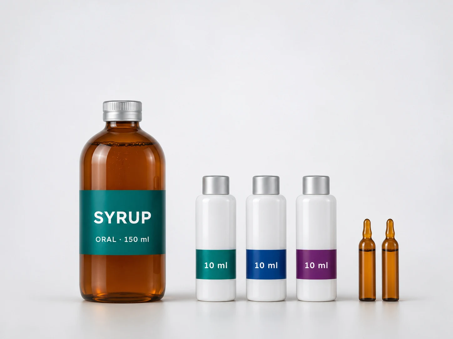
Pharmaceutical
Equipment cleaned
Process vessels, transfer lines, syrup and liquid lines
Main soils and risks
Active ingredients, excipients, allergens
CIP focus
Single-use CIP, purified water or WFI final rinse, GMP records
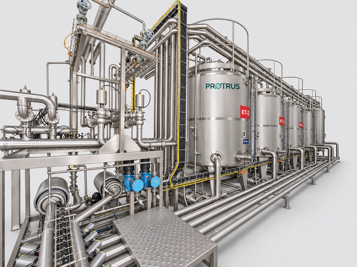
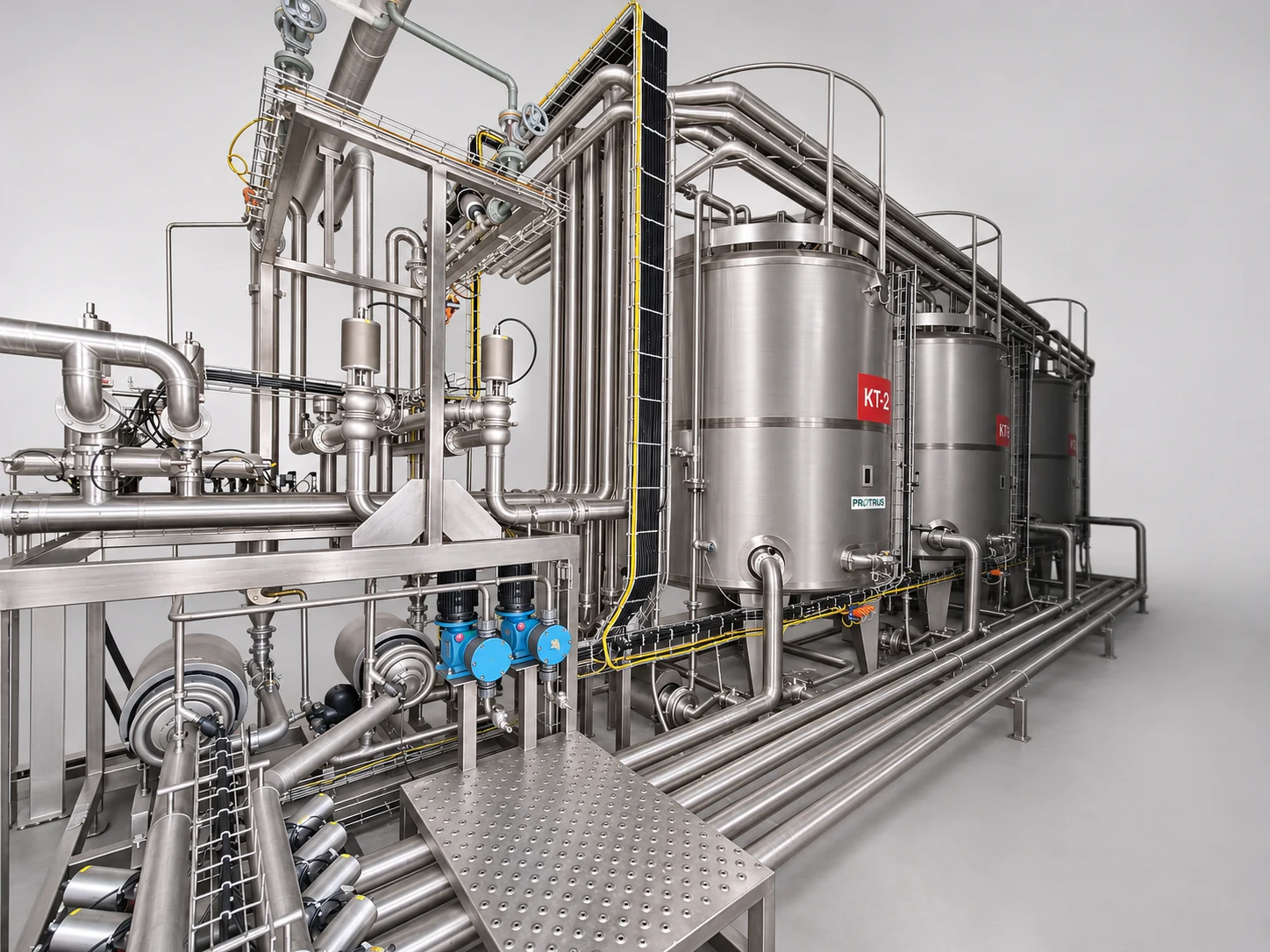
Process tank farm with valve matrix, cleaned by a central CIP station; inset: CIP supply and return lines.
CIP as Part of the Whole Plant
In a complete plant the CIP station is linked to every tank and line through valve matrices, swing bends or flow plates. Mix-proof valves keep product and cleaning solution safely apart, so one tank can be cleaned while its neighbor is filling.
Protrus plans CIP circuits together with the process, so each tank, line and heat exchanger has a defined route, a known flow and a recipe of its own. On a UHT unit, CIP runs by run time and heat transfer data.
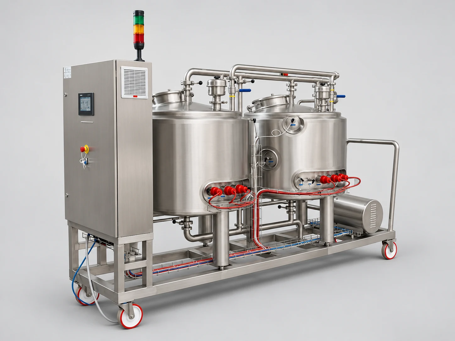
Mobile CIP unit with two heated tanks, pump and control panel on castors.
Mobile CIP Units
One compact CIP unit on castors for single machines, pilot plants and new lines, ready before the central CIP is installed.
2 × 500 L
insulated 316L tanks
3 × 7.5 kW
electric heating per tank
4 kW
centrifugal CIP pump
Cleaning Validation and Records
Validation proves that a recipe reaches the required hygiene level; routine verification shows that it still does. Protrus units record temperature, flow, conductivity and time for every step.
Supported checks
Frequently Asked Questions About CIP Units
Have a question about your CIP circuits, chemistry or sizing? Ask our process engineers.
Get a Quote
Plan Your CIP Unit with Protrus
Send us your plant layout or a list of the tanks, lines and heat exchangers to be cleaned, the longest CIP route, the products you run and how many circuits must be cleaned at the same time. Our engineers return the CIP circuit plan, tank and pump sizing, a P&ID, a 3D layout and a budget offer, for a mobile unit, a compact skid or a central multi-line CIP station.
Prefer email? info@protrus.com